


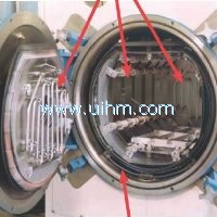
what is Furnace Brazing
2013/6/2 Views

What is brazing?
The term "brazing" can be applied to any process
which joins metals (of the same or dissimilar composition)
through the use of heat and a filler metal
with a melting temperature above 840° F (450° C),
but below the melting point of the metals being
joined. In furnace brazing, temperatures of 2050°
to 2100° F (1120° to 1150° C) and above are not
uncommon, especially when brazing stainless
steels with nickel-based filler metals or carbon
steel with copper filler metal. Other very high
temperature brazing applications include molybdenum
with pure nickel as the filler metal and cobalt
with a cobalt alloy filler metal.
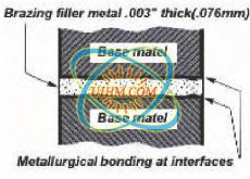
A successfully brazed joint often results in a metallurgical
bond that is generally as strong or stronger
than the base metals being joined. Modern brazing
technology has extended the definition to include
the bonding of metal to non-metallic substrates,
including glass and refractory materials. However,
this publication is limited to brazing of metals only,
and, specifically, furnace brazing of metals.
How does brazing join materials?
In furnace brazing, the parts or assemblies being
joined are heated to the melting point of the filler
metal being used. This allows the molten filler
metal to flow via capillary action into the closefitting
surfaces of the joint and to form an alloy of
the materials at the transition point upon solidification.
The base metals do not melt, but they can
alloy with the molten filler metal by diffusion to
form a metallurgical bond.
Because the metallurgical properties at the brazed
joint may differ from those of the base metals, the
selection of the appropriate filler metal is critical.
Depending on the desired properties of the application,
the brazing operation can be used to impart
a leaktight seal and/or structural strength, with
excellent appearance characteristics, in addition to
joining for the purpose of extending section length,
e.g., in piping or tubing materials.
The history of brazing
Brazing is the oldest method for joining metals,
other than by mechanical means. Initially, the
process was most popular for joining gold and silver
base metals. Lead and tin, as well as alloys of
gold-copper and silver-copper, were used as filler
metals because of their low melting points. Copper
hydrates and organic gums were added later
because of their reducing action, which helped to
minimize oxidation and improve the cosmetic
appearance of the joint. Metallic salts were also
used.
As with brazing, soldering does not involve the
melting of the base metals. However, the filler
metal used has a lower melting point (often
referred to as "liquidus") than that of brazing filler
metals (below approximately 840° F, or 450° C)
and chemical fluxes must be used to facilitate
joining.
In soldering operations, heat may be applied in a
number of ways, including the use of soldering
irons, torches, ultrasonic welding equipment,
resistance welding apparatus, infrared heaters, or
specialized ovens. A major advantage of soldering
is its low-temperature characteristic which minimizes
distortion of the base metals, and makes it
the preferred joining method for materials that
cannot tolerate brazing or welding temperatures.
However, soldered joints must not be subjected to
high stresses, as soldering results in a relatively
weak joint.
Welding, on the other hand, forms a metallurgical
joint in much the same way as brazing. Welding
filler metals flow at generally higher temperatures
than brazing filler metals, but at or just below the
melting point of the base metals being joined.
Figure 1. Eyeglass frames showing sequence of brazing
operations. (Photo courtesy of Handy & Harman)
Later, alloys of brass and copper were introduced
as filler metals because of their ability to produce
higher-strength joints in copper and steel structures,
which were also able to withstand high temperatures.
As brazing technology advanced, many
other filler metals have evolved.
Differences between soldering,
welding, and brazing
The joining techniques of soldering, welding, and
brazing have many similarities; however, each
process has its own characteristics and specific
indications for use. Generally, the criteria for
selecting one process over the other depend on the
physical and economic requirements of the base
metals and/or end-use of the assembly being
joined.
Fluxes are often employed to protect and assist in
wetting of the base-metal surfaces. Heating
sources include plasma, electron beam, tungsten
and submerged arc methods, as well as resistance
welding and, more recently, laser-based equipment
and even explosive welding.
A disadvantage of welding is its requirement for
higher temperatures, which melts the base metal
at the joint area and can result in distortion and
warpage of temperature-sensitive base metals and
stress-induced weakness around the weldment
area. It is generally used for joining thick sections
where high strength is required and small areas of
large assemblies (spot welding) where a degree of
base-metal distortion is acceptable. Welding can
also cause adverse changes in the mechanical and
metallurgical properties in the base metals'
Heat Affected Zone (HAZ), requiring further
corrective heat treatments.
7
www.uihm.com
In brazing operations, heat is generally supplied by
an oxyfuel-type torch (manual or automated), a
controlled-atmosphere or vacuum furnace, a
chemical dip (salt bath), or specialized equipment
using resistance, induction, or even infrared technologies.
Brazing is especially well suited to highvolume
production (automation) and for joining thin
sections and parts with complex geometries.
Furnace brazing, as opposed to flame brazing in
air, does not generally require a chemical flux,
which gives it a distinct advantage over welding
and soldering by reducing or eliminating the need
for cleaning the parts of flux residue.
Brazing filler metals flow at relatively low temperatures
and, thus, may be used with many popular
metals with minimal thermally-induced distortion
of the brazed parts. Furnace brazing is sometimes
problematic for very large assemblies because of
the size of the assembly relative to the brazing furnace
and the practicality and desirability of heating
the entire assembly to brazing temperatures. At
brazing temperatures, the metallurgical properties
of some temperature-sensitive base metals could
be compromised. However, furnace brazing is ideal
for joining complex assemblies.
Additional advantages of brazing include the ability
to:
• join dissimilar metals, porous metals,
powdered metals, and cast materials to
wrought metals, as well as non-metals to
metals
• join metals of varying section thickness
• maintain metallurgical properties of base
metals
• join fiber- and dispersion-strengthened
compounds
• work with extremely close production
tolerances
• provide reproducible results reliably,
compatible with accepted quality control
techniques
• obtain good results with minimal operator
training and less expensive equipment (than
welding)
Brazing as a joining technique has only a few disadvantages.
As mentioned previously, it may not be
suitable for extremely large assemblies. Also, metallurgical
concerns may dictate using an alternate
joining method. It must be remembered that the
physical and chemical properties of a brazed joint
can differ from that of the base and filler metals at
the joint transition, which is heterogeneous as a
result of the molecular nature of the bond. Also,
stresses caused by external loads are nonuniformly
distributed. These concerns are especially important
when brazing cold-worked or hardenable steels.
Table I compares the properties of soldered, welded,
and brazed joints.
Flame brazing vs. furnace brazing
Flame brazing is a process wherein the heat
required to melt and flow the filler metal is applied
locally to the joint area and is furnished by a fuel
gas flame, usually consisting of natural gas, acetylene,
hydrogen, or propane combusted with air or
oxygen (oxyfuel). The equipment used is similar to
that employed in gas torch welding. Flame brazing
requires a chemical flux to minimize oxidation that
would interfere with the integrity of the bond and to
aid in the filler metal flow (wettability). Use of a
chemical flux necessitates postbraze cleaning,
which is a secondary operation not generally
required of furnace brazements.
From a simple process standpoint, the two brazing
methods are identical: two base metal parts are
brought into close contact with one another in a
conventional joint configuration, i.e., butt or lap. A
suitable filler metal is placed along the seam or fed
into the joint along with a flux. The whole assembly
with the filler metal is then heated to a temperature
Table l. Differences between soldered, welded, and brazed joints
that allows the filler metal to liquify and fill the joint
gap via capillary action. Heat is removed and the
assembly is then cooled or allowed to cool to
ambient temperature before further processing.
Furnace brazing, however, offers distinct advantages
over flame brazing, especially in the areas of
control, automation, repeatability, and flexibility.
First commercialized in the early 1920's, furnace
brazing usually takes place in a controlled gaseous
atmosphere, in an evacuated chamber (vacuum
furnace), or in a specified low partial pressure
atmosphere (partial vacuum). As with flame brazing,
furnace-brazed parts are heated to a specific
brazing temperature until the filler metal flows. The
brazements are then cooled or "quenched," usually
in a different zone of the furnace, or in a separate
chamber, to produce the required material properties
in the finished assembly.
The advantages of furnace brazing are many,
including:
• Multiple joints on the same assembly can be
brazed simultaneously
• Complicated jigging is normally
unnecessary - usually gravity or minimal
fixturing is sufficient
• Undesirable atmosphere constituents
can be controlled or eliminated
• Multiple atmospheres or chambers make
various types of processing operations
possible
• The process is highly repeatable, ideally
lending itself to automated production and
data acquisition, e.g., SPC.
Joining Method Joint Strength Distortion Aesthetics
Soldering Poor None Good
Welding Excellent Likely Fair
Brazing Excellent Minimal Excellent
8
www.uihm.com
• Usually does not require
chemical fluxes
• Minimal or no post-braze
cleaning is required
• Provides close temperature
control, for optimum and
uniform results
The disadvantages of furnace brazing have to do
mainly with furnace issues, e.g., the cost of equipment
(versus flame brazing), higher power consumption,
and furnace maintenance requirements.
In addition, somewhat more attention has to be
paid to joint design because the brazing takes
place in the furnace chamber, and is not easily
observable. Also, a degree of process control skill
is required to manage the variables of atmosphere
composition, fuel flow, cross-contamination, outgassing,
and heating and cooling. Environmental
and safety considerations are also important in that
the brazing atmosphere precursors and their
byproducts may be toxic or explosive. Furnace
brazing is not optimal for low volume production of
components.
Brazing furnace configurations
Brazing furnaces may be gas-fired or electrically
heated, but the most common type of brazing furnace
uses electrical radiant heating elements to
transfer heat to the workload. Multiple thermocouples
are used in conjunction with automatic temperature
controllers to ensure that a uniform temperature
is maintained during brazing. In batch furnaces,
the option exists of attaching several
"work" thermocouples or embedding them in the
assembly being brazed, while multiple "control"
thermocouples typically monitor the temperature of
the atmosphere in the chamber from the furnace
wall.
For high-volume production, the most popular
equipment used for brazing is a continuous-type,
controlled atmosphere furnace, one that generally
relies on a continuous mesh-belt conveyor to move
the parts through the brazing cycle (Figure 2).
A variant of this "straight-through" design is the
"hump-back" furnace (Figure 3), which is used to
process stainless steels that require a highly reducing
atmosphere typically derived from a dissociated
ammonia atmosphere generation system (not
required for N2+H2 systems). The brazing chamber
in these furnaces is placed at a level above the
entry and exit points to concentrate the less dense
hydrogen atmosphere in the elevated brazing zone
of the furnace. This allows the denser nitrogen to
become concentrated at the entry and exit points of
the furnace, which then acts as a barrier to prevent
undesirable constituents from contaminating the
furnace atmosphere.
Other types of continuous furnaces are also used
for high-volume brazing, including mesh-belt, roller
hearth, and pusher configurations. Continuous-type
atmosphere brazing furnaces usually feature different
zones for preheating, brazing, and cooling, with
flame curtains at the entrance and exit to prevent
outside air from getting in and to combust the exiting
process gases.
The most common type of semi-continuous brazing
furnace is referred to as a retort furnace. In this
type of processing, a removable, sealed assembly
(retort) containing the brazing atmosphere and the
work to be brazed is placed into a box furnace and
the entire retort is heated to brazing temperature.
The process is termed semi-continuous since one
retort is being cooled while another is being
heated. Pusher mechanisms can also be employed
to "move" trays or baskets through the heating and
cooling cycle.
Figure 3. "Hump-back" furnace used to manufacture small assembled parts.
(Photo courtesy of Seco/Warwick Corp.)
9
www.uihm.com
Figure 5. Typical cold-wall vacuum furnace. (Photo courtesy of Ipsen International, Inc.)
Batch furnaces are also commonly used for brazing
operations and are well suited to small- to mediumvolume
production, especially where many types of
brazing operations are required. As its name
implies, a batch furnace brazes in "batches," or
one load at a time. Loading may take place from
the top, side, or bottom of the furnace.
Generally, batch atmosphere furnaces are of the
box-type design (Figure 4) which incorporates
entry and exit doors, a heating chamber, and a
water-jacketed cooling chamber.
Vacuum furnaces used for brazing are usually
batch-loaded, but may also be semi-continuous.
Depending on production requirements and furnace
design, vacuum furnaces may or may not
use retorts that are evacuated and heated to
brazing temperature.
Because of the inefficiencies relating to cooling
the large mass of the vacuum retort, vacuum
furnaces are usually limited to smaller charges.
Sometimes an inert or purge gas is introduced
into the retort to speed cooling. More commonly,
the vacuum brazing furnace is of the "coldwall"
type, which consists of a water-cooled vacuum
chamber with thermal insulation and heating
elements located within the chamber where
brazing takes place (Figure 5). Vacuum furnaces
are available in a variety of loading, material
handling, and work zone configurations.
10
www.uihm.com
A Look at Common Furnace
Brazements
Base metals
In considering whether furnace brazing is the right
joining technology for a specific application, the
characteristics of the base metals involved represent
one of the most important parameters. While
an extremely wide range of metals are adaptable
to brazing, certain base metals lend themselves
particularly well to brazing; others less so. In many
cases, the question seems to be not "Can I braze
these metals together?" but rather "How difficult
will it be?"
Common metals used for brazing are as follows:
• Copper and copper alloys
• Precious metals
• Low-carbon mild steels
• High-carbon steels
• Alloy and tool steels
• Cast iron
• Nickel and nickel alloys
• Cobalt and cobalt alloys
• Stainless steels
• Aluminum and aluminum alloys
• Magnesium and magnesium alloys
• Titanium, zirconium, and beryllium, and their
alloys
• Niobium, molybdenum, tantalum,
tungsten, and their alloys
Table II shows the relative ease with which the
most popular base metals can be brazed. The first
issues to consider when deciding whether or not to
braze certain metals have to do with the required
properties for the assembly's end use, most
notably strength, aesthetics, joint permanence, and
resistance to stress, corrosion, and extremes of
temperature.
Attention also must be paid to such factors as the
base metals' coefficients of thermal expansion,
especially when brazing components manufactured
from dissimilar metals where the coefficients of
expansion are different. If they differ widely, gaps
may open or close during the brazing process and
result in an unsatisfactory joint. The proper clearance
must be maintained at the brazing temperature.
More information regarding possible adverse
base metal effects can be found later under
"Troubleshooting."
Typical brazement parts/assemblies
Automotive applications use brazing extensively,
especially in the brazing of aluminum radiators,
which use tube-to-fin and tube-to-header joints.
The radiator cores are clad with a filler metal,
which flows at brazing temperature to complete the
joint. Vacuum is often used for brazing aluminum
because the use of a chemical flux is not required.
Table II. Relative ease of brazing various base metals.
However, recent developments in controlled atmosphere
technology have made it possible to braze
aluminum successfully in atmosphere furnaces
using so-called "aggressive" fluxes. These compounds
are usually fluoride- or chloride-based and
leave a corrosive residue on the parts which must
be cleaned after brazing in a dry nitrogen atmosphere.
Base Material Easy Fair Difficult
Copper •
Nickel •
Cobalt •
Alloys of Cu, Ni, and Co •
Steels •
Precious metals •
Aluminum •
Tungsten •
Molybdenum •
Tantalum •
Refractory alloys
(>5% metal oxide)
•
Cast iron •
Tungsten carbide •
Titanium •
Stainless steels •
Zirconium •
Beryllium •
Alloys of Ti, Zr, and Be •
Titanium carbide •
11
www.uihm.com
Figure 6. Typical brazed honeycomb structure for aerospace
applications. (Photo courtesy of Ipsen International,
Inc.)
A very effective fluxing agent for removing surface
aluminum oxides from aluminum in the brazing
process is marketed by the Alcan Corporation
under the tradename Nocolok®. This fluoride-based
flux, as well as similar formulations recently made
available, relies on potassium instead of sodium,
which leaves a non-corrosive residue. These fluxes
can be applied to joint surfaces without any postbraze
cleaning necessary.
Other automotive aluminum brazing applications
include aluminum pistons, engine blocks, heat
exchangers, and evaporators.
The aircraft and aerospace industry relies on
brazed honeycomb structures (Figure 6) because of
their high strength-to-weight ratios. Other applications
include wing and jet engine components
made from nickel and cobalt-based alloys, stainless
steel, and titanium.
Brazing is widely used in pipe and tube applications
to extend length, fabricate shapes, join dissimilar
materials, and ensure a water- or pressure-tight
joint (Figure 7). Common base metals include aluminum
and its alloys, copper and its alloys, steel,
and stainless steel.
In the electronics industry, brazing is used to produce
metal-to-ceramic and metal-to-glass seals for
electrical components, vacuum tubes, and sensing
devices (Figure 8, page 13). Microwave reflectors,
satellites, cameras, and sophisticated instrumentation
are all applications in which brazing plays a
part. Common base metals used include oxygenfree
copper, nickel, stainless steel, copper-nickel
alloys, iron-nickel-cobalt alloys, molybdenum, and
tungsten. Refractory materials include alumina, fosterite,
and sapphire ceramics.
Brazing is often used to join carbides of metals that
have been bonded with cobalt or nickel, such as
tungsten carbide, titanium carbide, tantalum carbide,
and chromium carbide to metal parts, especially
in cutting tools (Figure 9, page 13).
While the subject of this publication is furnace brazing
of metals, mention should be made of brazing
applications involving ceramics (aluminum oxide)
such as lamp housings and spark plugs, and
graphite (carbon), used in bushings, nozzles, and
electric motor brushes. These materials pose special
challenges and specific technologies have been
developed to enable them to be brazed. In the case
of ceramics, a sintered-metal powder process,
sometimes called the moly-manganese or Mo-Mn
process, is employed to metallize the surface of the
ceramic part. Other techniques include vapor deposition
of metal onto ceramic prior to brazing or
using so-called "active" filler metals that are specially
alloyed to promote wetting on ceramics.
Like ceramic, graphite is inherently difficult to wet
using common filler metals, and techniques have
been developed to coat its surface with a metallic
or intermetallic layer to enable brazing to take
place. Because graphite oxidizes at very low temperatures
(750° F or 400° C), it must be brazed in
a vacuum or high-purity, inert atmosphere.
Another brazing application that is becoming more
and more popular is so-called "sinter brazing." In
this process, "green" parts that have been pressed
together are simultaneously brazed and sintered in
the furnace hot zone. A typical sinter-brazing application
is the joining of "hubs" to transmission
gears.
Figure 7. Typical brazed pipe/tube applications. (Photo
courtesy of Handy & Harman)
12
www.uihm.com
Joint design and preparation
While furnace brazing usually eliminates the need
for cleaning parts to remove flux and surface contaminants
after processing, it is extremely important
that pre-cleaning and/or degreasing take
place. This ensures that joint surfaces are free of
oxides, oil, and other undesirable artifacts that
could interfere with proper wetting and filler metal
flow. In certain applications, the components to be
brazed are pre-processed in an attempt to break
down the transparent oxide on the surface of the
parts. Distortion is a concern. In other applications,
a nickel "flash" or plate is added as a coating to
promote braze adhesion.
In addition to cleaning, the gap between the base
metals being joined (referred to as clearance, or
the distance between the opposing, or faying, surfaces)
is critical for many reasons, especially when
joining two dissimilar metals, because of the differences
in the metals' temperature coefficients of
expansion. At brazing temperatures, this difference
can cause the joint clearance to widen or narrow
unacceptably. Therefore, the brazements must be
designed to have the proper clearance at brazing
temperature.
Proper joint clearance, sometimes called "fit-up," is
also important because it has a bearing on the final
mechanical performance of the joint, such as stress
loading. Generally speaking, clearances should be
as tight and as uniform as possible to optimize capillary
attraction and minimize the chance of voids
occurring in the molten filler metal. Table III (page
14) lists some recommended joint clearances for
typical filler metal types used in furnace brazing,
according to American Welding Society classifications.
Types of joints
There are literally dozens of different joint configurations;
however, most are merely variations on the
two basic joint types used in furnace brazing: lap
joints and butt joints.
While it is beyond the scope of this publication to
provide detailed information on joint selection, here
is a brief summary of the most popular joint types
and their respective advantages. The term "lap
joint" is derived from its overlapping characteristic
(Figure 10, page 14) which acts to increase joint
strength by providing additional brazed surface area
and section thickness. Sometimes this additional
thickness is unwanted and, in fact, can cause a
concentration of stress at the joint ends. Lap joints
are easily fabricated and require minimal or no
fixturing.
Butt joints are not as strong as lap joints. In fact, it
should always be assumed that a brazed butt joint
will be weaker than that of the base metal used
(except for diffusion-brazed nickel filler metal
joints, where the brazed joint strength will
generally equal that of the base metal). This characteristic
should be given serious consideration
when anticipating the joint's expected service
requirements. A variation of the butt joint known as
a "scarf" joint adds strength, but is more problematic
to prepare and fixture. Another variation combines
the advantages of both joints and is referred
to as a "butt-lap" joint. Figure 10 (page 14) shows
some typical joints and variations.
Figure 8. Typical metal-to-glass brazements used in the electronics
industry. (Products courtesy of Century Seals, Inc.)
Figure 9. Typical carbide cutting tools brazed to metal in a brazing furnace. (Photo
courtesy of Handy & Harman)
13
www.uihm.com
According to the American National Standards
Institute (ANSI) and AWS C3.6, "Specification for
Furnace Brazing,"there are four classifications of
furnace-brazed joints, based on two criteria:
"...design requirements and the consequences of
their failure." They are (directly quoted):
Class A
Class A joints are those joints subjected to high
stresses, cyclic stresses, or both, the failure of
which could result in significant risk to persons or
property, or could result in a significant operational
failure.
Class B
Class B joints are those joints subjected to low or
moderate stresses, cyclic stresses, or both, the
failure of which could result in significant risk to
persons or property, or could result in a significant
operational failure.
Class C
Class C joints are those joints subjected to low or
moderate stresses, cyclic stresses, or both, the
failure of which would have no significant,
detrimental effect.
No Class Specified
When no class is specified on the engineering
drawing or other applicable document approved by
the Organization Having Quality Responsibility,
Class A requirements shall apply. However,
because of the confusion which can result, all
engineering drawings referencing this specification
should state the class of the brazed joint in the
braze joint symbol. Symbols shall be in accordance
with AWS A2.4 "Symbols for Welding, Brazing, and
Nondestructive Examination."
Sound practice dictates that strict attention be paid
to these guidelines during the design stage and
when selecting the base metals and filler metals to
be used during brazing. Know the end-use requirements
of your assembly well, match your
materials to the job, and test the brazement
thoroughly under real-world conditions to ensure
the best result and avoid potential problems later.
Selecting a base metal
Usually the first consideration when selecting a
base metal, just as in designing a joint, is strength.
Brazed joints must withstand the same stresses
and service requirements as the final assembly.
Consideration, then, must be given to any change in
base-metal strength caused by the brazing process.
As previously mentioned, cold-worked metals are
often weakened by brazing, and hardenable metals
may lose their hardenable properties. Also, these
metals generally cannot be satisfactorily heat treated
after brazing. Therefore, in selecting a suitable
base metal for an application where joint strength
must not be compromised, choose a metal with an
intrinsic strength much higher than its service
requirements or one that can be successfully heattreated
after brazing.
A list of typical base metals is provided in Table IV
(pages 15 and 16).
Table III. Recommended clearances for typical furnace brazing filler metals
AWS Classification Recommended Joint Clearance
BAlS group 0.000-0.002" for vacuum brazing
0.002-0.008" for lap lengths < 0.25"
0.002-0.010" for lap lengths > 0.25"
BCuP group 0.001-0.005" for joint lengths <1.0"
0.007-0.015" for joint lengths >1.0"
BAg group 0.000-0.002" for atmosphere brazing*
BAu group 0.000-0.002" for atmosphere brazing*
BCu group 0.000-0.002" for atmosphere brazing*
BNi group 0.002-0.005" for general applications
0.000-0.002" for atmosphere brazing
*For maximum strength, a press fit of 0.001 per inch of diameter is recommended.
14
www.uihm.com
Table IV. Typical base metals
Base Metal Class Composition Notes
Copper and copper alloys Oxygen-bearing coppers
Electrolytic tough pitch (ETP) copper
Deoxidized and oxygen-free coppers
Special coppers
High coppers
Copper-zinc alloys (brass)
Leaded brasses
Copper-tin alloys (phosphor bronzes)
Copper-aluminum alloys (aluminum bronzes)
Copper-silicon alloys (silicon bronzes)
Copper-nickel alloys
Copper-nickel-zinc alloys (nickel silvers)
Precious metals Gold and gold alloys
Platinum group metals
Silver and silver alloys
Plated materials
Low-carbon, low-alloy, Low carbon (less than 0.30% carbon)
and tool steels Low alloy (less than 5% total alloy)
Free machining leaded steels
Carbon (alloy) tool steels
High-speed tool steels
Cast iron Gray
Ductile
Malleable
Nickel and nickel alloys Commercially pure nickel
Nickel-copper alloys
Solid-solution-strengthened nickel super alloys
Precipitation-hardenable nickel super alloys
Oxide-dispersion-strengthened (ODS) nickel alloys
Cobalt and cobalt alloys Iron-based cobalt alloys
Nickel-based cobalt alloys
Cobalt-based alloys
Stainless steels Austenitic (non-hardenable)
Ferritic (non-hardenable)
Martensitic (hardenable)
Precipitation-hardened
Duplex
15
www.uihm.com
Aluminum and aluminum alloys High-purity aluminum Must be brazed in vacuum
Low alloy aluminum furnace with Nocolok®
Magnesium-silicon aluminum alloys or an aggressive flux at
Wrought and high-alloy aluminum high temp/low dewpoint.
Magnesium and magnesium alloys M1A alloys only Low solidus
temperature prevents
other magnesium
alloys from being
furnace brazed.
Titanium, zirconium, and beryllium Reactive to oxygen to
form stable oxides.
High solubility for oxygen,
nitrogen, and hydrogen
at elevated temperatures.
Must be brazed in
high-purity inert gas
(argon or helium) or high
vacuum to avoid
embrittlement.
Reacts with carbon (sometimes
added intentionally) at
elevated temperatures
to form carbides.
Refractory metals
Niobium, molybdenum, tantalum, tungsten Controlled brazing
environment critical.
Niobium and tantalum are
similar to titanium and zirconium
in regard to pick-up of oxygen,
nitrogen, hydrogen, and carbon.
Molybdenum and tungsten can
be brazed in an exothermic
atmosphere with a +70° F dewpoint
or any better atmosphere,
such as argon, pure dry hydrogen,
or high vacuum. Often brazed to
dissimilar metals.
16
www.uihm.com
Figure 11. Typical brazing filler metal preforms. (Photo courtesy of Handy & Harman)
Once the requirements for strength are met, other
considerations for base metal selection can be
evaluated. These criteria include such parameters
as aesthetics (surface appearance), electrical conductivity,
weight, and resistance to corrosion, wear,
temperature, and pressure. Some brazements may
have to meet stated pressure/strength criteria for
hermetic sealing to military or other specification
standards. In addition to considerations of the base
metal's physical properties, cost and suitability for
automated production may also need to be
addressed.
Selecting a filler metal
Obviously, care must be taken when choosing a
filler metal to ensure compatibility with the base
metal from a metallurgical standpoint. However, the
correct filler metal formulation must also fit the
requirements of the brazing operation and the
overall economics of the final application. Some
filler metals should not be used in combination
with certain base metals, e.g., copper-phosphorus
filler metals with ferrous, nickel, or nickel-alloy
base metals.
Generally, a filler metal must meet the same
requirements as the base metal insofar as the
parameters of strength, corrosion resistance,
oxidation resistance, and temperature are concerned.
In addition to these service requirements,
the filler metal must possess the desired wetting
and flow characteristics for the base metals being
brazed, have compatible melting properties with
low volatility, and exhibit no adverse metallurgical
reaction at brazing temperatures.
Criteria to consider in selecting a filler metal:
• Base metal/joint temperature
requirements
• Flow/wettability characteristics
• Joint clearance (temperature
coefficient)
• Strength at service temperature
• Hardness (fracture resistance)
• Galvanic corrosion resistance
• Stress (fatigue) resistance
• Electrical properties
• Heat transfer properties
• Fillet appearance
• Cost of material
Filler metals are available in several configurations
designed to accommodate various brazing environments,
with the most popular (in furnace brazing)
being the "preform" type. Preforms, used commonly
in high-volume production brazing, are filler
metals that have been stamped or shaped into
washers, rings, shims, formed strips, or wire to fit
over the joint being brazed. In furnace brazing, the
preforms are preplaced in the brazements and held
in place by friction or gravity. Figure 11 shows
some typical filler metal preforms.
Other filler metal configurations used in furnace
brazing include paste, powder, ribbons, spray, and
sheet (foil). Sheet-type filler metals offer improved
joint strength for brazing applications with a large
joint surface area or "sandwich" type joints.
When using a filler-metal paste, a secondary cleaning
operation may be required to remove binder
residue. The proper formulation is essential, especially
in vacuum brazing, where sometimes a partial
pressure is required to prevent vaporization of the
filler metal and resulting bad brazements. Another
method of applying filler metal is by cladding,
most commonly used for aluminum brazing. A thin
layer of a lower-melting-point aluminum alloy is
pressure-bonded to base aluminum alloys; the filler
metal then melts during the brazing operation.
Pre-assembly and fixturing
To ensure the tightest clearance suitable for the
filler metal in a given joint, to control the direction
of molten filler metal flow, and to eliminate any
chance of misalignment during processing, thought
must be given to how the brazement will be held
together prior to, during, and after brazing.
Generally speaking, a fixture should be as simple as
possible to make it easy to remove from the parts
after brazing. However, complex assemblies may
require more elaborate means of pre-assembly,
such as tack welding or tie rods.
When brazing dissimilar metals, it may be necessary
to control the ambient temperature to ensure
optimum joint clearance. Similarly, brazing fixtures
used for brazing base metals with a high thermal
coefficient of expansion, such as aluminum or
magnesium, require special attention. In many
cases, however, parts (especially sheets and lap
joints) can rely on gravity, weights, or simple
support blocks or clamps to maintain proper fit-up
(Figure 12, page 18).
17
www.uihm.com
When brazing in vacuum or a protective gas atmosphere,
it is important to use fixture materials that
are stable at brazing temperatures, since outgassing
can contaminate the brazing atmosphere.
For example, graphite, which is sometimes used as
a fixturing material, can react with water vapor or
other oxygen-containing compounds to form carbon
monoxide, which can diffuse into some metals at
brazing temperatures, causing unwanted carburization.
Also, a brazement with base metals such as
Ni, Fe, Ti, Zr, etc., and their alloys should not be
placed directly on graphite fixtures as they will pick
up carbon, possibly forming an undesirable liquid
phase. On the other hand, graphite gets stronger at
high temperature and is very stable (although fragile).
The fact that it is easily machinable also lends
itself to use in fixturing small parts.
Some brazements can be fabricated to be "self-jigging,"
i.e., having interlocking tabs or other physical
features designed into the assembly to ensure
proper fit-up for brazing.
Wettability
As applied to brazing, the term "wetting" refers to
the spreading and adhering properties of a filler
metal when brought to a liquid state. A filler metal's
wettability, therefore, is a qualitative measure of its
ability to bond with a given base metal at brazing
temperature. While every filler metal has a distinct
wettability with regard to every base metal, there
are many factors that can interfere with its optimal
wetting properties, even when care is taken (as it
should be) to match filler metal and base metal
carefully.
Wetting is not the same as capillary attraction.
Wetting relates to the ability of the molten filler
metal to spread uniformly and diffuse into or alloy
with the base metals. Capillary attraction, while
enhanced by high wettability, is the property that
draws the molten filler metal into the joint clearances.
The most important factor in ensuring both optimal
wettability and good capillary attraction is a clean
surface, free of oxides, grease, and other contaminants.
Anything that interferes with the filler metalbase
metal interface, even at the molecular level,
can adversely affect wettability, filler metal flow,
and the integrity of the joint. A surface that is too
smooth, however, can cause poor adhesion and
Figure 12. Typical self-fixturing methods for brazed assemblies. (From Brazing Handbook, American
Welding Society. Used with permission.)
inhibit filler metal flow. Surface roughness actually
enhances wettability, but a surface that is too rough
may adversely affect joint strength.
Before brazing, parts can be cleaned in a number of
ways. Abrasive mechanical cleaning, such as filing,
grinding, surface blasting, and wire brushing are
used to remove difficult surface oxides. Mechanical
methods, such as tumbling, that use alumina oxide
as the abrasive medium can worsen the problem
and should not be used. For less problematic materials
or for secondary cleaning, baths or special
equipment are used, the most common being:
• Chemical solvents
• Vapor degreasers
• Emulsifying agents
• Phosphate-type acids
• Alkaline cleaners
• Electrolytic cleaners
• Acid dipping and pickling
• Molten salt bath pickling
Mechanical agitation is generally used to assist in
the cleaning process, which can be accomplished
by stirring, active circulation, or ultrasonic energy.
Thermal treatments can also be used which reduce
oxides and remove contaminants by bringing the
parts to near or above brazing temperature.
Parts may also be precoated with special finishes,
or electroplated, to prevent oxide formation and aid
in wettability. Precoating is more common with
metals that readily oxidize, such as aluminum and
titanium. Sometimes, it helps to apply a precoating
when brazing dissimilar metals to ensure that the
filler metal flows evenly to both.
In protective-atmosphere furnace brazing, the
atmosphere itself (usually high-purity hydrogen or
vacuum) can act as a flux or reducing/dissociating
agent; however, it is not a substitute for precleaning.
Also, in atmosphere brazing where the controlled
environment affords maximum wetting,
braze flow inhibitors are sometimes used to "mask"
off areas of the parts, such as holes and threads,
where excess flow of the filler metal would be
undesirable. These commercially available so-called
"stop-off" materials are usually applied by brush or
hypodermic needle. Precise application is required
so as not to interfere with desired braze flow and to
minimize any post-braze cleaning required to
remove the stop-off material.
18
www.uihm.com
Down Attachment
- DownloadAttach1: what is Furnace Brazing.pdf Clicks
Good
(2)
100.0%
Bad
(0)
0.0%


")


Newest Comment
No Comment
Post Comment