RESONANT CHARGING
The connection of a Tank capacitor across an inductively ballasted supply creates a resonant circuit.
| | The resonant frequency of this arrangement is determined by the values of the ballast inductance L and the tank capacitance C. The frequency is not affected by the winding resistance R or any resistive ballast added. (Typically the resonant frequency will lie between 10Hz and 500Hz.) |
| | Resonance will occur regardless of whether the transformer is ballasted at the primary or the secondary, but it is easier to understand if we assume the ballast inductance is in series with the secondary side of the transformer. If this assumption is made then we can consider the HV transformer as presenting a stiff HV supply so the circuit can be simplified to get that shown on the left. The values of L and R are derived from an actual 10kv/100mA Neon sign transformer. |
The graphs below show the frequency response of a 10kv/100mA neon sign transformer with a "matched" 32nF tank capacitor. This capacitor was chosen deliberately to form a resonant circuit at exactly the 50Hz line frequency.
C is chosen such that F=1 / 2*pi*sqrt(L*C) = 50Hz.
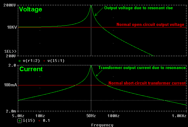
On the top graph, the RED line shows the normal open circuit voltage from the transformer. The GREEN line shows the final voltage across the transformer when the capacitor is connected across it and resonance takes place. A frequency response graph such as this shows how the voltage varies with different supply frequencies.
Notice how the voltage rises above the normal open-circuit voltage of the transformer as the line frequency approaches 50Hz. The maximum occurs at 50Hz, and the voltage then falls away as the frequency is increased further. (The simulation predicts a final voltage of nearly 200KV if a 50Hz supply is used ! In practice, failure of either the transformer or capacitor would stop the resonant rise effect long before such a high voltage could develop.)
The bottom graph shows how the current supplied by the transformer is affected by the formation of the resonant circuit. The RED line shows the normal short-circuit current that the neon can supply, and the GREEN line shows the current supplied to the "matched" capacitor at different supply frequencies.
Notice how the current is below the rated current when the line frequency is well below or well above 50Hz. At frequencies either side of 50Hz the circulating current is equal to the 100mA rated current of the transformer. As the line frequency approaches 50Hz the circulating current increases. The simulation predicts nearly 2 amps at 50Hz. This is 20 times the current which the shunted transformer is designed to allow into a short circuit, and would result in destructive heating of the windings.
Both of these graphs show what happens at the WORST CASE when a MATCHED CAPACITOR is used, and there is NO SPARK GAP to provide somewhere for the energy to go. If a suitably set spark gap is used which fires regularly then energy would be removed from the resonant system before the voltages and currents could build to such a damaging level.
This example is included here because it demonstrates four things:-
-
It shows how important it is to use correctly set safety gaps to prevent excessive voltage rise if using a capacitor which is close to "matched" size.
-
It shows that the tank capacitance effectively cancels out the ballast inductance near the resonant frequency. In this example at 50Hz the current is 2A which is the result of current limiting by only the winding resistance. The inductive ballasting effect of the magnetic shunts is eliminated.
-
It shows that current will be drawn from the supply even though no power is being taken from the system yet. (There is no spark gap to discharge the capacitor.) The current flowing is reactive current and represents energy "sloshing" in and out of the tank capacitor as it is charged in opposing directions by the positive and negative cycles of the supply.
-
It shows the "shape" of the LC resonant response before the effect of a spark gap is introduced.
The addition of a correctly set spark gap will limit the amount of voltage rise permitted whilst still getting the benefit of the increased charging current.
Resonant charging can take place with both neon sign transformers and inductively ballasted power transformers. The only difference is that the ballast is built into the neon transformer. Power transformers, however, have much lower internal losses. This results in a higher Q value and causes more intense voltage and current rises around the resonant frequency.
Due to the intensity of the resonant rise effect, it is not always desirable to use a "matched" capacitor which causes resonance at exactly the line frequency. The graph below shows the effect of using "smaller than resonant" and "larger than resonant" capacitors on the same 10kv/100mA neon supply. (The supply still has no spark gap connected, only the tank capacitor.)
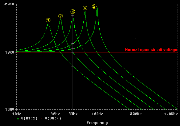
Line 1 shows a 128nF cap (4x "Matched" size) Fres = 25.0 Hz
Line 2 shows a 64nF cap (2x "Matched" size) Fres = 35.4 Hz
Line 3 shows a 32nF cap (1x "Matched" size) Fres = 50.0 Hz
Line 4 shows a 16nF cap (1/2 "Matched" size) Fres = 70.7 Hz
Line 5 shows a 8nF cap (1/4 "Matched" size) Fres = 100 Hz
The white crosses indicate the final voltage that would occur due to resonant rise with a 50Hz supply if the spark gap was absent or not firing. It is easy to see that the voltage rise is much lower with a capacitor which is not of "matched" size. The transformer and capacitor may have a chance of surviving this overvoltage if the spark gap was set too wide to fire. Line 3 with the matched cap represents a certain death situation if the spark gap was to misfire !
The white crosses on lines 1 and 2 show the effect of using capacitors which are bigger than matched size. As the capacitor is made larger the voltage tends towards zero. (The supply is becoming less capable of charging the bigger capacitor.)
The white crosses on lines 4 and 5 show the effect of using capacitors which are smaller than matched size. As the capacitor is made smaller the voltage tends towards the normal open-circuit rating of the transformer. (The transformer is becoming more lightly loaded.)
Line 2 represents a special case. The 2x "Matched" capacitor value causes no resonant rise at 50Hz and the final voltage is equal to what the open circuit voltage of the transformer would normally be. This is the only capacitor value which results in no voltage rise at the supply frequency, and is used for this reason to examine "Inductive Kick" in a separate section below.
the key to making use of resonant rise in a Tesla Coil power supply is in achieving just the desired voltage increase and no more. This can be done by careful setting of a 100BPS synchronous rotary spark gap. In the resonant charging system energy sloshes back and forth between the ballast inductance and the tank capacitor building on every cycle as power is supplied by the transformer. The firing point of the rotary gap needs to be set so that a significant amount of energy is removed from the charging system whilst it is in the tank capacitor. This energy goes into the Tesla Coil primary winding to produce good sparks and prevents the level of energy in the charging system from sky-rocketing to dangerous levels.
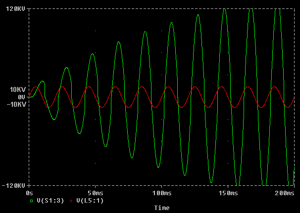
The result of two different timings (phase settings) of a 100BPS synchronous rotary gap are shown below:
In this first graph the rotary phase is set incorrectly. Although the capacitor is charging to a high enough voltage, the firing point is too late and occurs too far after the voltage peak. As a consequence little energy is being removed from the resonant charging circuit and the voltage rises up to a dangerous level in a matter of milliseconds.
In the graph below the rotary phase is set near to the optimum position. Firstly, notice that the voltage scale is now more realistic. The spark gap is firing when the capacitor is at its peak voltage, and delivers more power into the Tesla Coil system. Because a lot of energy is being removed from the capacitor on every firing of the gap, there is almost no resonant rise due to energy build up in the charging circuit.
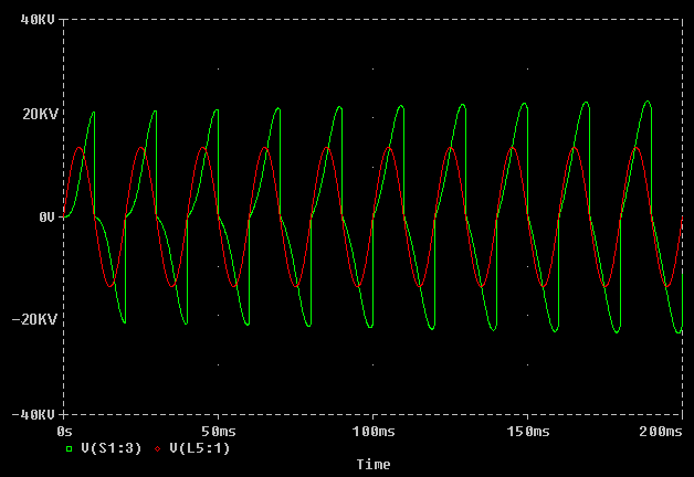
The difference in rotary timing between these examples is less than 2ms, and it is easy to see that the first case would be catastrophic if a good safety gap were not employed to clamp the resonant voltage rise. In practice a good rotary setting would lie somewhere in between the two examples above. If the components are delicate and overvoltage must be minimised then the timing will be close to the bottom case. If the components are robust and more overvoltage can be tolerated then the timing can be delayed to get more resonant rise and move closer to the top example. This needs to be done with caution as changing the phase of a 100BPS gap will give some combinations with very powerful resonant rise, and high current draw !
Because resonant voltage rise thrives on time, (time required for the voltage to build-up,) it is worth considering what would happen if our spark gap was to accidentally miss a firing. If a rotary gap misfires, there cannot be another firing until the next time that the electrodes are aligned. This means that when a firing is missed there is twice as long between discharges of the tank capacitor, and this allows the voltage to ring up to a higher voltage.
Computer based simulation packages such as PSpice are ideal for predicting what would actually happen in such circumstances without risking any expensive components. The graph below shows the effect of a correctly set up 100BPS synchronous rotary gap, which fails to fire at t = 160ms. The energy which is not removed from the system at this point remains in the charging system and causes the voltage to be higher at the next firing of the spark gap.
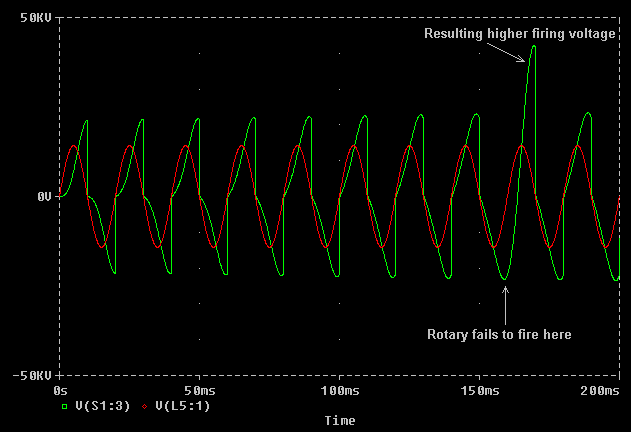
Notice that there is no overvoltage at the actual point where the firing was missed, but the capacitor voltage swings back aggressively heading towards a much increased positive voltage before the next firing. The voltage spike here is around twice the normal peak voltage seen by the tank capacitor and transformer and could represent a hazard to a marginally rated component.
Note that this example uses a "matched" capacitor which gives very strong resonance at the line frequency, and considerable overvoltage occurs after only one missed firing. If the spark gap is set too wide and there are several adjacent missed firings then the voltage will rise higher still. It is therefore essential that a correctly set safety gap is fitted when using a matched capacitor, especially when combined with a low speed rotary.
The 200BPS synchronous rotary is more tolerant of incorrect phase settings and missed firings. This is because at 200BPS the resonant system is discharged twice as often. The time in which any resonant build-up can occur is therefore halved, however there are disadvantages to this too. This is discussed in more detail in another section.
Wide static gaps,
Resonant charging does not only apply to systems incorporating a rotary spark gap. Resonant charging is the means by which a wide static gap can fire and give good performance.
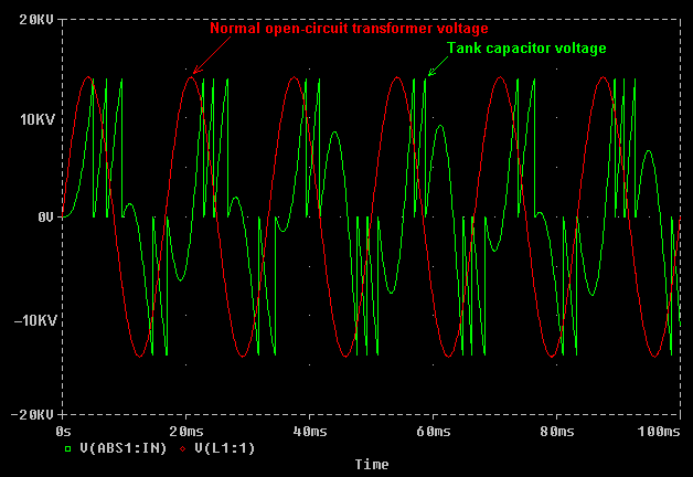
A closely spaced static spark gap will fire at a relatively low voltage, causing the tank capacitor to be recharged many times per supply cycle. In the graph, below a simulation was run with a static gap set to fire at 14Kv (This is just under the peak open-circuit voltage of the transformer, so it would just fire when connected across the transformer alone.) The firing of the static gap is fairly erratic, with roughly 2 to 3 firings per half cycle of the supply. This erratic firing is quite normal. In this case the average firing rate is around 250BPS.
In the graph below the static gap was "opened-up" to fire at 22KV, which is higher than the normal peak output voltage of the transformer. It can only fire due to resonant rise, so the time between firings is greater. In this case there are between 1 and 2 firings per half cycle on average. Therefore the average break rate has dropped to around 150BPS. The energy in each bang however has increased due to the increased firing voltage.
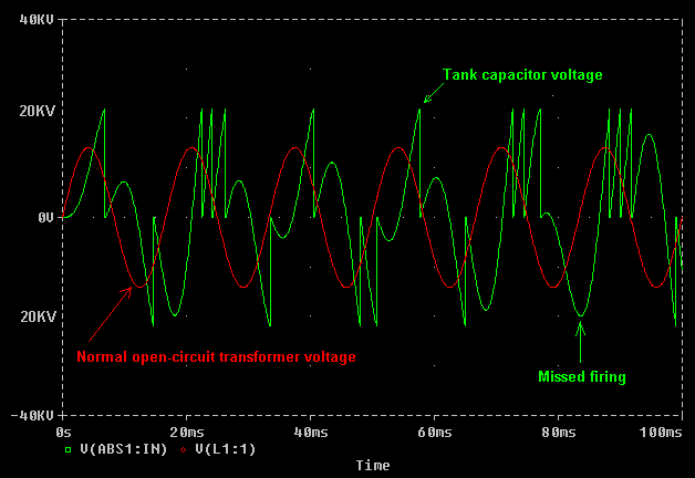
In the example above the firing voltage is 57% higher than the previous example. Since Energy stored in the tank capacitor increases with the square of the voltage, the bang energy is 2.46 times that in the first example. But the firing rate in the second example is lower. In fact the firing rate is roughly 150 compared to 250 in the previous example. In summary, widening the static gap has caused the bang energy to increase by 2.46 times, and the firing rate to change by a factor of 0.6 This gives an overall increase in power throughput of nearly 50% ! That is why wide static spark gaps give good performance, but also stress components by allowing a large resonant voltage rise to occur.


Newest Comment
No Comment
Post Comment