In recent years this plant is using hardening with preceding induction heating for more
than 50% of the total amount of heat-treated parts. These are mainly tractor parts made from
45, 40Kh, 38KhGS, and 33KhS steels. The overwhelming majority of parts (85% of all items)
undergo heat-treatment within the machining lines. The parts made in small series are
treated on induction devices in the mechanical shop, in the repair-mechanical shop, and in
the experimental section of the electric heating laboratory.
The induction heating prior to hardening is carried out mainly at frequencies of 8, i0~
and 70 kHz.
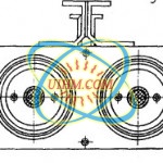 The induction devices with vacuum-tube oscillators are fitted with hardening attachments
or general-purpose hardening tanks with an adjustable holder for the hardening attachments.
The holder is a horizontally mounted fork which moves in the vertical direction for securing
the device at the required level in relation to the inductor.
For heating parts in the inductors fed from machine generators mainly hardening machines
are used which consist of a universal heating station (UHS) mounted on a common frame with a
hardening transformer, condenser battery and devices for control and cooling; the contactor
cuboard with a high-frequency disconnecting switch, contactor measuring transformers; a
large hardening device (mounted on the frame) or a special tank, on which a small hardening
device is mounted, enclosed in a casing with a hole for the part. The space under the casing
is connected to aventilation system provided for letting out smoke and steam produced during
the hardening process.
When oil is used as the hardening liquid, the tank is equipped with a pump for feeding
oil into the sprayer or in some other cooler.
Sprayer-cooling by oil or cooling by a flow of oil* delivered in the inductor is used
mainly for cooling parts made from steels 40Kh and 38KhGS.
In some cases for cooling parts from alloyed steel in plants use is made of cyclic cooling
(this method has been taken over from the Chelyabinsk Tractor Plant) where the section
of the parts heated for hardening is rotated near the sprayer, cooling at each moment of time
only a section of the heated surface. Here each surface element is periodically exposed for
a short time to the action of the hardening medium, while during the remaining part of the
cycle it is heated by heat transfer from inside the part. The variation of the rotational
speed of the part and of the size of the section being cooled makes possible to change the
cooling regime. It should be noted that cooling is of a pulsating nature only on the surface
and in the metal layers close to the surface. With the decreasing distance from the
surface the pulsation amplitude decreases while the cooling rate becomes averaged.
The plant makes wide use of the centralized feed system of hardening machines by highfrequency
current. Each step making use of this system has a transformer substation with
mechanical frequency transformers. The capacity of such a substation is 200-12,500 kW. The
generators mounted in the substation work in parallel on common bushbars in which the voltage
is maintained by a thyristor-transistor voltage control unit. Common busbars supply all
hardening machines of the shop normally using different power.
The installed capacity of consumers exceeds the output of the substation and to avoid
overloading of generators use is made of a system for limiting the load or of selective connection
of machines.
The plant has developed and makes use of original technological processes and equipment.
They include, in particular, the process of continuously successive hardening of the rear
semiaxis [i], and hardening of holes in the rotating inductor-transformer and of plates of
the gear box fork in forced condition.
Related
Induction Heating multi wire bundles of rotor with different shape induction coils
induction heating bolt
induction heating steel rod by UM-40AB-HF
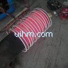
induction heating end of pipeline by 160kw induction heater
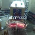
induction heating cambered work-piece by 160KW power supply
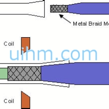
Induction heating for Plastic Reflow With Catheter Tubing
© Copyright 2025. uihm.com All Rights Reserved.

Newest Comment
No Comment
Post Comment