HEAT TREATMENT WITH INDUCTION HEATING OF WITHIN PIPES
Views Send Enquiry
Electrically welded pipes with an external diameter of 16-102 mm made from corrosionresistant
steels of the austenitic class after having been made on argon-arc welding mill(AAW) are at present heat-treated in electric transfer type roller furnaces working without a protective atmosphere by the following method: heating to I050-I070°C, holding for 4-5 min,
cooling in air. This regime produces the following mechanical properties of the weld and
base metal corresponding to GOST 11068-81: ot g 560 N/mm2; 65 ~ 36%.
Heat-treatment in electric roller furnaces has the following shortcomings. Prolonged
heating of pipes at high temperatures results in grain growth as well as in oxidation of the
metal which, in turn, requires prolonged etching and an increased consumption of the etching
solution during the chemical processing of pipes. The heaters of electric furnaces have a
short life with the result that furnaces must be shut down every month for repair. The
operation of these furnaces requires a high specific power consumption caused by heating.up
the furnaces after repairs as well as by idling of the furnaces during standstill.
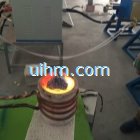
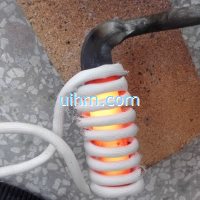
To a considerable extent these shortcomings can be eliminated by high-speed induction
heating within the pipe welding machine line instead of heat treatment in the furnace. The
parameters of the induction heat-treatment were determined on the basis of the results obtained
in an investigation of pipes with a diameter of 18-43 mm, wall thickness of 1.5, and
a length of 360 mm made from steels 10KhI8NIOT and 12KhI8NIOT on the laboratory machine. The
power of this machine is I00 kW, frequency 8 kHz.
A short pipe was heated in the inductor to I000-1250°C with intervals at 50°C at a rate
of 60°/sec. At each temperature being investigated a holding of 5-60 sec was introduced whereupon
the pipe was cooled in water. On specimens made from short lengths of pipe metallographic
investigationswere carried out and the mechanical properties of the base metal and the weld
were determined. Figure 1 shows that ~5 of the welded joint increases within the temperature
range 1000-1150°C whereupon at I180-I190°C it does practically no more change and at temperatures
above 1200°C it begins to fall. A metallographic analysis showed that in the case of
rapid heating to II00-1200°C in the absence of prolonged holding at a certain temperature
no marked grain growth was observed, both in the ‘base metal’ and in the weld zone. At temperatures
above 1200°C the grain increases from No. 8 in the initial condition to No. 6.
During induction heating with the duration of holding increasing at the final temperature from
5 to 30 sec the ~5 increases, while during a further reduction in holding it begins to fall.
However, in all cases, ~5 is considerably higher than that required by GOST 11068-81. On
this basis it can be said that during induction heating the required value of ~5 is reached
at a minimum holding of up to 5 sec.
The illustration also shows that at temperatures above 1200°C the ultimate strength approaches
the minimum permissible value. On the basis of our investigations the following
heating regime was selected for the mill: temperature I130-I190°C, the maximum possible holding
time was chosen taking into account the location of the mill equipment (4-5 sec), and
cooling was by a water spray.
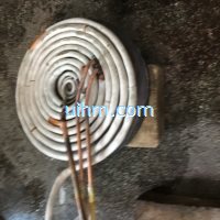
On the machines ADS “10-60″ and “20-102″ between the unit and the first part of the calibration
mill there is a gap whose length is about 1200 mm where the inductor, sprayer, and
guides are placed.
The investigations were carried out on an ADS “20-102″ machine of the Moscow Pipe Works
[i]. The power supply to the inductor was from the induction system of the mass-produced
induction apparatus I34-200/8 supplying 200 kW at a frequency of 800 kHz. For 40-102-mm-diameter pipes inductors were produced with an inner diameter of 93, ii0, 120, and 135 mm
with 5-8 windings. The total length of the device is 1040 mm. From the sprayer the pipe
enters into the calibration mill whereupon it is cut to measured lengths. Pipes measuring
57 × 3; 76 × 2; 89 x 3; and 102 × 3 mm were heat treated within the mill line; they were
made from 10KhI8NIOT steel. The temperature of pipes at the inductor outlet was measured by
means of a radiation pyrometer TERA-50 in combination with the potentiometer KSP-3M; the
speed of the pipe travel and the induction unit power were read on the mill control instruments.
The degree of metal oxidation was determined by weighing (before and after etching) the
pipe ends cut from pipes after heat treatment in the induction device and electric roller
furnace OKB-854A. Table 1 gives the technical characteristics of the induction device. It
can be seen that the maximum pipe temperature variation at the inductor outlet is ±30°C. The
accuracy with which the specified temperature is maintained depends on the fluctuations of
the pipe speed, the variation of the strip over the length, as well as on the stability of
the inductor voltage. The effect of these parameters determines the heating accuracy within
±30°C. With these figures taken into account 1160 ± 30°C was accepted as the heating temperature.
The mechanical delivery properties of the pipes processed in the induction apparatus
are shown in Table 2. The tensile tests were carried out according to GOST 10006-80 on
longitudinal specimens – segments cut from the base metal with a weld in the middle. It can
be seen that the inductive heat treatment permits to obtain the required 65 and ~t values,
both in the weld zone and in the base metal.
The results of delivery tests showed that after this type of heat-treatment the pipes
withstand the required hydraulic pressure of 6 MPa applied by bending and flattening as well
as widening to a cone of 30 ° with an increase of the external diameter exceeding on average
by 20% the values specified in GOST 11068-81.
The heating rate of pipes was 120-190 K/sec which produces a fine-grain structure and
leads to the reduction of metal oxidation to 0.2-0.22% (percentage of mass) as against 0.5-
0.55% by heat treatment in electric resistance furnace OKB-854A.
The specific power consumption from the mains is 310-380 kWh/ton which is by 40-50 kWh/ton
less than in the electric furnace.
In the case of correct adjustment of the calibration mill through which the pipes pass
after induction heat treatment their geometry is somewhat different from that of pipes which
have not been treated before in the calibration mill. However, when changing to processing
pipes by heat-treatment, an additional device must be introduced into the calibration mill
line because of higher plasticity of the metal after heat treatment.
Heating of a pipe in the inductor causes its elongation and its consequent deflection
from the horizontal axis which is the larger the smaller the pipe diameter. This deflection
can be partially compensated by increasing the pipe extension by greater roller speed in the
calibration mill. A more accurate centering of the pipe can be effected by means of roller
guides mounted in front of the inductor and behind the sprayer. The installation of such
guides is indispensable in the case of up to 40-mm-diameter pipes. Larger pipes are more rigid and with the pipe speed taken into account, in the calibration mill the deviation of
the pipe from the longitudinal axis does not exceed 1-2 mm. In this case no special guides are needed.
When using induction heat treatment within the mill line, there is no need for additional
attendants. The heating control system contains a facility for automatic disconnecting of
the inductor when the welding mill stops. However, when the welding mill is in operation
and an irregularity occurs within the welding process, the inductor and sprayer must be disconnected
by means of pushbuttons provided. If this is not done, the inductor will overheat
and the number of areas with holes in the weld increases and water getting through these
holes into the sPrayer and from there into the welding unit will spoil the welding process.
This calls for permanent attendance by the welder at the control desk of heating and welding.
For complete automation of the welding process it is necessary to design a system for
monitoring the quality of the weld and for automatic disconnection of the inductor and sprayer
in the case of any breakdown of the welding process.
The profit resulting from the introduction of induction heat-treatment into the line
of pipe welding mills of argon-arc welding in the Moscow Pipe Works will be 75,600 rubles.
CONCLUSION
Induction heat treatment of corrosion-resistant steel pipes in the line of an argon-arc
welding mill produces a fine-grain structure of the base metal and weld, ensures the mechanical
properties of pipes as specified in GOST 11068-81:65 ~ 36%, ot ~ 560 N/mm 2 and also makes
possible the oxidation of the metal by 0.33%, reduces the timeand consumption of the etching
solution during chemical processing, and saves power.
 HEAT-TREATMENT WITH INDUCTION HEATING OF PIPES WITHIN THE PIPE
Related Content

induction brazing SS steel by handheld induction coil
induction melting silicon and steel
magnesium oxide acidic furnace for induction melting glass
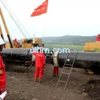
induction preheating gas pipeline by full air cooled clamp induction coil and DSP induction heater
induction melting with Titanium alloy pot by customized induction coil

induction melting aluminium for casting wire wheel
induction heating steel plate by pancake induction coil
induction heating steel knife
Hot

Induction Heating multi wire bundles of rotor with different shape induction coils
induction heating bolt
induction heating steel rod by UM-40AB-HF
induction heating end of pipeline by 160kw induction heater
induction heating steel plates by auto feed system with 120KW induction heater
induction heating cambered work-piece by 160KW power supply
Induction heating for Plastic Reflow With Catheter Tubing
U shape induction coil for heating hole
Newest Comment
No Comment
Post Comment