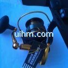
Induction Soldering satellite antennas
Views Send Enquiry
Objective Soldering steel onto GPS body for phone antenna
Material Thin copper foil 0.3mm (0.01 in) thick Ceramic body 12mm (0.47 in.) long x 7mm (0.28 in.) wide
Temperature 200º C (392º F)
Frequency 371 kHz
Process Time 5 seconds
Equipment • Power of 6 kW induction heating system, equipped with a remote workhead containing (2).33μF capacitors (for a total of .66 μF).
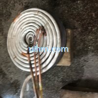
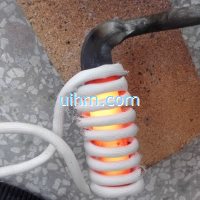
• Two coils (one for each stage of process) designed and developed specifically for this application. The first stage uses a two-turn solenoid coil with a 15mm (0.6 in) ID and the second stage uses a plate coil, 25
mm (1 in.) dia. with a 6mm (0.24 in.) hole.
Process
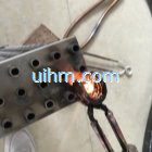
Stage 1: A two-turn solenoid coil is used to heat the top end of a GPS antenna. Solder paste is used to solder the walking stick loop to the copper foil.
Stage 2: A plate coil is used to heat the bottom part of the GPS to solder a top hat to the copper foil and also the bottom part of the walking stick.
Results/Benefits Induction heating benefits:
• increased production rate due to speed of heating
• higher quality vs. a soldering iron due to precision and repeatability
• cost savings due to reduced scrap and higher quality production

Soldering satellite antennas
Related Content
induction brazing SS steel by handheld induction coil
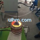
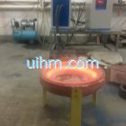
induction melting silicon and steel
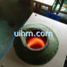
magnesium oxide acidic furnace for induction melting glass
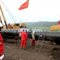
induction preheating gas pipeline by full air cooled clamp induction coil and DSP induction heater
induction melting with Titanium alloy pot by customized induction coil
induction melting aluminium for casting wire wheel
induction heating steel plate by pancake induction coil
induction heating steel knife


Newest Comment
No Comment
Post Comment