Induction Coil Design and Fabrication
2013/4/8 Views
The inductor is similar to a transformer primary, and the workpiece is equiva-lent to the transformer secondary
. Therefore, several of the charac-teristics of transformers are useful in the development of guidelines for coil design.
One of the most important features of transformers is the fact that the ef-ficiency of coupling between the wind-ings is inversely proportional to the square of the distance between them.
In addition, the current in the primary of the transformer, multiplied by the number of primary turns, is equal to the current in the secondary, multiplied by the number of secondary turns.
Be-cause of these relationships, there are several conditions that should be kept in mind when designing any coil for induction heating:
1) The coil should be coupled to the part as closely as feasible for maxi-mum energy transfer.
It is desirable that the largest possible number of magnetic flux lines intersect the work-piece at the area to be heated.
The denser the flux at this point, the higher will be the current generated in the part.
2) The greatest number of flux lines in a solenoid coil are toward the center of the coil.
The flux lines are concentrated inside the coil, providing the maximum heating rate there.
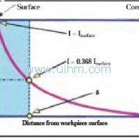
3) Because the flux is most concen-trated close to the coil turns them-selves and decreases farther from them, the geometric center of the coil is a weak flux path. Thus, if a part were to be placed off center in a coil, the area closer to the coil turns would in-tersect a greater number of flux lines and would therefore be heated at a higher rate, whereas the area of the part with less coupling would be heated at a lower rate; the resulting pattern is shown schematically in Fig2 This effect is more pronounced in high-fre-quency induction heating.
4) At the point where the leads and coil join, the magnetic field is weaker; therefore, the magnetic center of the inductor is not necessarily the geomet-ric center.
This effect is most appar-ent in single-turn coils. As the number of coil turns increases and the flux from each turn is added to that from the previous turns, this condition be-comes less important. Due to the im-practicability of always centering the part in the work coil, the part should be offset slightly toward this area.
In addition, the part should be rotated, if practical, to provide uniform exposure.
5) The coil must be designed to pre-vent cancellation of the magnetic field.
The coil on the left in Fig. 3 has noinductance because the opposite sides of the inductor are too close to each other.
Putting a loop in the inductor (coil at center) will provide some inductance.
The coil will then heat a conducting material inserted in the opening.
The design at the right pro-vides added inductance and is more representative of good coil design.
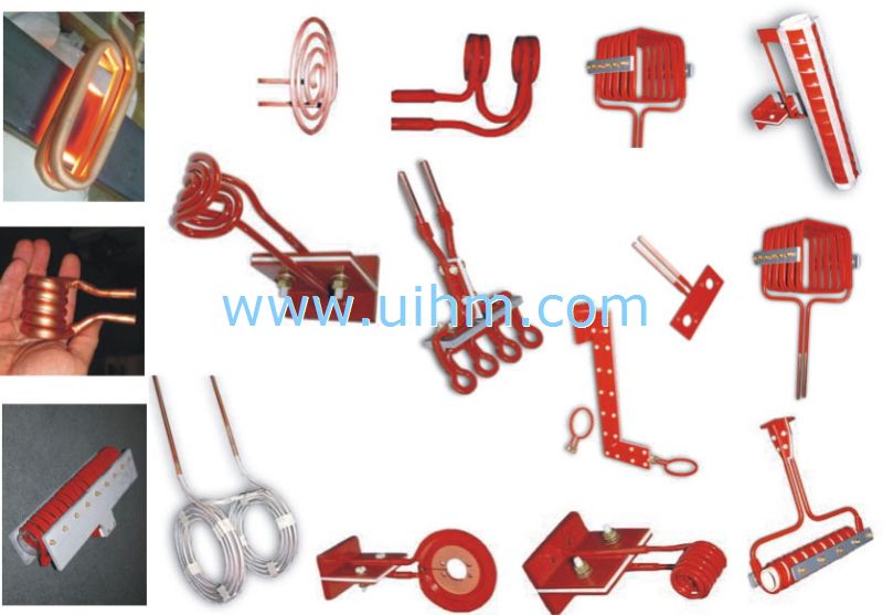
Because of the above principles, some coils can transfer power more readily to a load because of their abil-ity to concentrate magnetic flux in the area to be heated. For example, three coils that provide a range of heating behaviors are:<0095> a helical solenoid, with the part or area to be heated located within the coil and, thus, in the area of greatest magnetic flux;

Down Attachment
- DownloadAttach1: induction coil design and fabrication.pdf Clicks


Newest Comment
No Comment
Post Comment