Base details of High Frequency Induction Heating
Views Send Enquiry
Introduction
Induction heating is a non-contact heating process. It uses high frequency electricity to heat materials that are electrically conductive. Since it is non-contact, the heating process does not contaminate the material being heated. It is also very efficient since the heat is actually generated inside the workpiece. This can be contrasted with other heating methods where heat is generated in a flame or heating element, which is then applied to the workpiece. For these reasons Induction Heating lends itself to some unique applications in industry.
How does Induction Heating work ?
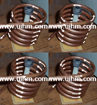
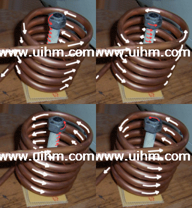
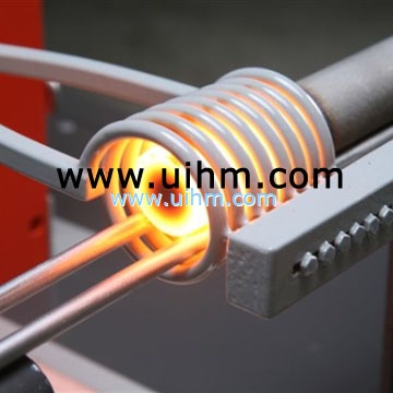
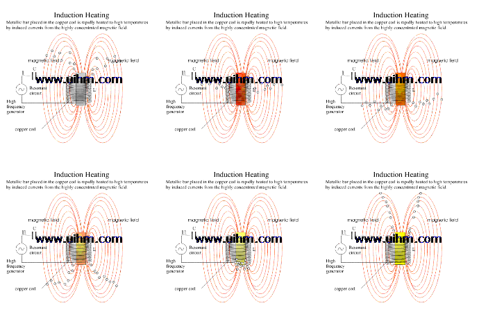
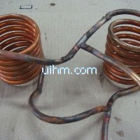
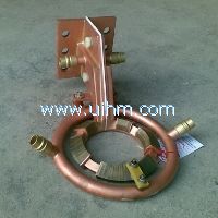
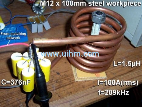
| A source of high frequency electricity is used to drive a large alternating current through a coil. This coil is known as the work coil. See the picture opposite. The passage of current through this coil generates a very intense and rapidly changing magnetic field in the space within the work coil. The workpiece to be heated is placed within this intense alternating magnetic field. Depending on the nature of the workpiece material, a number of things happen... | |
| The alternating magnetic field induces a current flow in the conductive workpiece. The arrangement of the work coil and the workpiece can be thought of as an electrical transformer. The work coil is like the primary where electrical energy is fed in, and the workpiece is like a single turn secondary that is short-circuited. This causes tremendous currents to flow through the workpiece. These are known as eddy currents. In addition to this, the high frequency used in induction heating applications gives rise to a phenomenon called skin effect. This skin effect forces the alternating current to flow in a thin layer towards the surface of the workpiece. The skin effect increases the effective resistance of the metal to the passage of the large current. Therefore it greatly increases the heating effect caused by the current induced in the workpiece. | |
(Although the heating due to eddy currents is desirable in this application, it is interesting to note that transformer manufacturers go to great lengths to avoid this phenomenon in their transformers. Laminated transformer cores, powdered iron cores and ferrites are all used to prevent eddy currents from flowing inside transformer cores. Inside a transformer the passage of eddy currents is highly undesirable because it causes heating of the magnetic core and represents power that is wasted.)
And for Ferrous metals ?
For ferrous metals like iron and some types of steel, there is an additional heating mechanism that takes place at the same time as the eddy currents mentioned above. The intense alternating magnetic field inside the work coil repeatedly magnetises and de-magnetises the iron crystals. This rapid flipping of the magnetic domains causes considerable friction and heating inside the material. Heating due to this mechanism is known as Hysteresis loss, and is greatest for materials that have a large area inside their B-H curve. This can be a large contributing factor to the heat generated during induction heating, but only takes place inside ferrous materials. For this reason ferrous materials lend themselves more easily to heating by induction than non-ferrous materials.
It is interesting to note that steel looses its magnetic properties when heated above approximately 700°C. This temperature is known as the Curie temperature. This means that above 700°C there can be no heating of the material due to hysteresis losses. Any further heating of the material must be due to induced eddy currents alone. This makes heating steel above 700°C more of a challenge for the induction heating systems. The fact that copper and Aluminium are both non-magnetic and very good electrical conductors, can also make these materials a challenge to heat efficiently. (We will see that the best course of action for these materials is to up the frequency to exaggerate losses due to the skin effect.)
What is Induction Heating used for ?
Induction heating can be used for any application where we want to heat an electrically conductive material in a clean, efficient and controlled manner.
One of the most common applications is for sealing the anti-tamper seals that are stuck to the top of medicine and drinks bottles. A foil seal coated with "hot-melt glue" is inserted into the plastic cap and screwed onto the top of each bottle during manufacture. These foil seals are then rapidly heated as the bottles pass under an induction heater on the production line. The heat generated melts the glue and seals the foil onto the top of the bottle. When the cap is removed, the foil remains providing an airtight seal and preventing any tampering or contamination of the bottle's contents until the customer pierces the foil.
Another common application is "getter firing" to remove contamination from evacuated tubes such as TV picture tubes, vacuum tubes, and various gas discharge lamps. A ring of conductive material called a "getter" is placed inside the evacuated glass vessel. Since induction heating is a non-contact process it can be used to heat the getter that is already sealed inside a vessel. An induction work coil is located close to the getter on the outside of the vacuum tube and the AC source is turned on. Within seconds of starting the induction heater, the getter is heated white hot, and chemicals in its coating react with any gasses in the vacuum. The result is that the getter absorbs any last remaining traces of gas inside the vacuum tube and increases the purity of the vacuum.
Yet another common application for induction heating is a process called Zone purification used in the semiconductor manufacturing industry. This is a process in which silicon is purified by means of a moving zone of molten material. An Internet Search is sure to turn up more details on this process that I know little about.
Other applications include melting, welding and brazing or metals. Induction cooking hobs and rice cookers. Metal hardening of ammunition, gear teeth, saw blades and drive shafts, etc are also common applications because the induction process heats the surface of the metal very rapidly. Therefore it can be used for surface hardening, and hardening of localised areas of metallic parts by "outrunning" the thermal conduction of heat deeper into the part or to surrounding areas. The non contact nature of induction heating also means that it can be used to heat materials in analytical applications without risk of contaminating the specimen. Similiarly, metal medical instruments may be sterilised by heating them to high temperatures whilst they are still sealed inside a known sterile environment, in order to kill germs.
What is required for Induction Heating ?
In theory only 3 things are essential to implement induction heating:
- A source of High Frequency electrical power,
- A work coil to generate the alternating magnetic field,
- An electrically conductive workpiece to be heated,
Having said this, practical induction heating systems are usually a little more complex. For example, an impedance matching network is often required between the High Frequency source and the work coil in order to ensure good power transfer. Water cooling systems are also common in high power induction heaters to remove waste heat from the work coil, its matching network and the power electronics. Finally some control electronics is usually employed to control the intensity of the heating action, and time the heating cycle to ensure consistent results. The control electronics also protects the system from being damaged by a number of adverse operating conditions. However, the basic principle of operation of any induction heater remains the same as described earlier.
Practical implementation
In practice the work coil is usually incorporated into a resonant tank circuit. This has a number of advantages. Firstly, it makes either the current or the voltage waveform become sinusoidal. This minimises losses in the inverter by allowing it to benefit from either zero-voltage-switching or zero-current-switching depending on the exact arrangement chosen. The sinusoidal waveform at the work coil also represents a more pure signal and causes less Radio Frequency Interference to nearby equipment. This later point becoming very important in high-powered systems. We will see that there are a number of resonant schemes that the designer of an induction heater can choose for the work coil:
Series resonant tank circuit
The work coil is made to resonate at the intended operating frequency by means of a capacitor placed in series with it. This causes the current through the work coil to be sinusoidal. The series resonance also magnifies the voltage across the work coil, far higher than the output voltage of the inverter alone. The inverter sees a sinusoidal load current but it must carry the full current that flows in the work coil. For this reason the work coil often consists of many turns of wire with only a few amps or tens of amps flowing. Significant heating power is achieved by allowing resonant voltage rise across the work coil in the series-resonant arrangement whilst keeping the current through the coil (and the inverter) to a sensible level.
This arrangement is commonly used in things like rice cookers where the power level is low, and the inverter is located next to the object to be heated. The main drawbacks of the series resonant arrangement are that the inverter must carry the same current that flows in the work coil. In addition to this the voltage rise due to series resonance can become very pronounced if there is not a significantly sized workpiece present in the work coil to damp the circuit. This is not a problem in applications like rice cookers where the workpiece is always the same cooking vessel, and its properties are well known at the time of designing the system.
The tank capacitor is typically rated for a high voltage because of the resonant voltage rise experienced in the series tuned resonant circuit. It must also carry the full current carried by the work coil, although this is typically not a problem in low power applications.
Parallel resonant tank circuit
The work coil is made to resonate at the intended operating frequency by means of a capacitor placed in parallel with it. This causes the current through the work coil to be sinusoidal. The parallel resonance also magnifies the current through the work coil, far higher than the output current capability of the inverter alone. The inverter sees a sinusoidal load current. However, in this case it only has to carry the part of the load current that actually does real work. The inverter does not have to carry the full circulating current in the work coil. This is very significant since power factors in induction heating applications are typically low. This property of the parallel resonant circuit can make a tenfold reduction in the current that must be supported by the inverter and the wires connecting it to the work coil. Conduction losses are typically proportional to current squared, so a tenfold reduction in load current represents a significant saving in conduction losses in the inverter and associated wiring. This means that the work coil can be placed at a location remote from the inverter without incurring massive losses in the feed wires.
Work coils using this technique often consist of only a few turns of a thick copper conductor but with large currents of many hundreds or thousands of amps flowing. (This is necessary to get the required Ampere turns to do the induction heating.) Water cooling is common for all but the smallest of systems. This is needed to remove excess heat generated by the passage of the large high frequency current through the work coil and its associated tank capacitor.
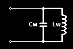
In the parallel resonant tank circuit the work coil can be thought of as an inductive load with a "power factor correction" capacitor connected across it. The PFC capacitor provides reactive current flow equal and opposite to the large inductive current drawn by the work coil. The key thing to remember is that this huge current is localised to the work coil and its capacitor, and merely represents reactive power sloshing back-and-forth between the two. Therefore the only real current flow from the inverter is the relatively small amount required to overcome losses in the "PFC" capacitor and the work coil. There is always some loss in this tank circuit due to dielectric loss in the capacitor and skin effect causing resistive losses in the capacitor and work coil. Therefore a small current is always drawn from the inverter even with no workpiece present. When a lossy workpiece is inserted into the work coil, this damps the parallel resonant circuit by introducing a further loss into the system. Therefore the current drawn by the parallel resonant tank circuit increases when a workpiece is entered into the coil.
Impedance matching
Or simply "Matching". This refers to the electronics that sits between the source of high frequency power and the work coil we are using for heating. In order to heat a solid piece of metal via induction heating we need to cause a TREMENDOUS current to flow in the surface of the metal. However this can be contrasted with the inverter that generates the high frequency power. The inverter generally works better (and the design is somewhat easier) if it operates at fairly high voltage but a low current. (Typically problems are encountered in power electronics when we try to switch large currents on and off in very short times.) Increasing the voltage and decreasing the current allows common switch mode MOSFETs (or fast IGBTs) to be used. The comparatively low currents make the inverter less sensitive to layout issues and stray inductance. It is the job of the matching network and the work coil itself to transform the high-voltage/low-current from the inverter to the low-voltage/high-current required to heat the workpiece efficiently.
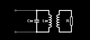
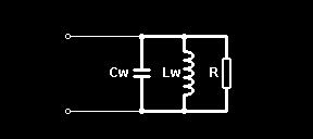
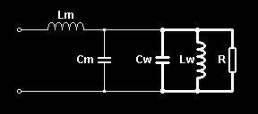
| We can think of the tank circuit incorporating the work coil (Lw) and its capacitor (Cw) as a parallel resonant circuit. This has a resistance (R) due to the lossy workpiece coupled into the work coil due to the magnetic coupling between the two conductors. See the schematic opposite. | |
| In practice the resistance of the work coil, the resistance of the tank capacitor, and the reflected resistance of the workpiece all introduce a loss into the tank circuit and damp the resonance. Therefore it is useful to combine all of these losses into a single "loss resistance." In the case of a parallel resonant circuit this loss resistance appears directly across the tank circuit in our model. This resistance represents the only component that can consume real power, and therefore we can think of this loss resistance as the load that we are trying to drive power into in an efficient manner. | |
When driven at resonance the current drawn by the tank capacitor and the work coil are equal in magnitude and opposite in phase and therefore cancel each other out as far as the source of power is concerned. This means that the only load seen by the power source at the resonant frequency is the loss resistance across the tank circuit. (Note that, when driven either side of the resonant frequency, there is an additional "out-of-phase" component to the current caused by incomplete cancellation of the work coil current and the tank capacitor current. This reactive current increases the total magnitude of the current being drawn from the source but does not contribute to any useful heating in the workpiece.)
The job of the matching network is simply to transform this relatively large loss resistance across the tank circuit down to a lower value that better suits the inverter attempting to drive it. There are many different ways to achieve this impedance transformation including tapping the work coil, using a ferrite transformer, a capacitive divider in place of the tank capacitor, or a matching circuit such as an L-match network.
| In the case of an L-match network it can transform the relatively high load resistance of the tank circuit down to something around 10 ohms which better suits the inverter. This figure is typical to allow the inverter to run from several hundred volts whilst keeping currents down to a medium level so that standard switch-mode MOSFETs can be used to perform the switching operation. The L-match network consists of components Lm and Cm shown opposite. | |
The L-match network has several highly desirable properties in this application. The inductor at the input to the L-match network presents a progressively rising inductive reactance to all frequencies higher than the resonant frequency of the tank circuit. This is very important when the work coil is to be fed from a voltage-source inverter that generates a squarewave voltage output. Here is an explanation of why this is so…
The squarewave voltage generated by most half-bridge and full-bridge circuits is rich in high frequency harmonics as well as the wanted fundamental frequency. Direct connection of such a voltage source to a parallel resonant circuit would cause excessive currents to flow at all harmonics of the drive frequency! This is because the tank capacitor in the parallel resonant circuit would present a progressively lower capacitive reactance to increasing frequencies. This is potentially very damaging to a voltage-source inverter. It results in large current spikes at the switching transitions as the inverter tries to rapidly charge and discharge the tank capacitor on rising and falling edges of the squarewave. The inclusion of the L-match network between the inverter and the tank circuit negates this problem. Now the output of the inverter sees the inductive reactance of Lm in the matching network first, and all harmonics of the drive waveform see a gradually rising inductive impedance. This means that maximum current flows at the intended frequency only and little harmonic current flows, making the inverter load current into a smooth waveform.
Finally, with correct tuning the L-match network is able to provide a slight inductive load to the inverter. This slightly lagging inverter load current can facilitate Zero-Voltage-Switching (ZVS) of the MOSFETs in the inverter bridge. This significantly reduces turn-on switching losses due to device output capacitance in MOSFETs operated at high voltages. The overall result is less heating in the semiconductors and increased lifetime.
In summary, the inclusion of an L-match network between the inverter and the parallel resonant tank circuit achieves two things.
- Impedance matching so that the required amount of power can be supplied from the inverter to the workpiece,
- Presentation of a rising inductive reactance to high frequency harmonics to keep the inverter safe and happy.
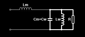
| Looking at the previous schematic above we can see that the capacitor in the matching network (Cm) and the tank capacitor (Cw) are both in parallel. In practice both of these functions are usually accomplished by a single purpose built power capacitor. Most of its capacitance can be thought of as being in parallel resonance with the work coil, with a small amount providing the impedance matching action with the matching inductor (Lm.) Combing these two capacitances into one leads us to arrive at the LCLR model for the work coil arrangement, which is commonly used in industry for induction heating. | |
The LCLR work coil
This arrangement incorporates the work coil into a parallel resonant circuit and uses the L-match network between the tank circuit and the inverter. The matching network is used to make the tank circuit appear as a more suitable load to the inverter, and its derivation is discussed in the section above.
The LCLR work coil has a number of desirable properties:
- A huge current flows in the work coil, but the inverter only has to supply a low current. The large circulating current is confined to the work coil and its parallel capacitor, which are usually located very close to each other.
- Only comparatively low current flows along the transmission line from the inverter to the tank circuit, so this can use lighter duty cable.
- Any stray inductance of the transmission line simply becomes part of the matching network inductance (Lm.) Therefore the heat station can be located away from the inverter.
- The inverter sees a sinusoidal load current so it can benefit from ZCS or ZVS to reduce its switching losses and therefore run cooler.
- The series matching inductor can be altered to cater for different loads placed inside the work coil.
- The tank circuit can be fed via several matching inductors from many inverters to reach power levels above those achievable with a single inverter. The matching inductors provide inherent sharing of the load current between the inverters and also make the system tolerant to some mismatching in the switching instants of the paralleled inverters.
For more information about the behaviour of the LCLR resonant network see the new section below labelled "LCLR network frequency response."
Another advantage of the LCLR work coil arrangement is that it does not require a high-frequency transformer to provide the impedance matching function. Ferrite transformers capable of handling several kilowatts are large, heavy and quite expensive. In addition to this, the transformer must be cooled to remove excess heat generated by the high currents flowing in its conductors. The incorporation of the L-match network into the LCLR work coil arrangement removes the necessity of a transformer to match the inverter to the work coil, saving cost and simplifying the design. However, the designer should appreciate that a 1:1 isolating transformer may still be required between the inverter and the input to the LCLR work coil arrangement if electrical isolation is necessary from the mains supply. This depends whether isolation is important, and whether the main PSU in the induction heater already provides sufficient electrical isolation to meet these safety requirements.
Conceptual schematic
The system schematic belows shows the simplest inverter driving its LCLR work coil arrangement.
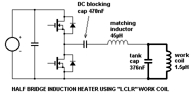
The inverter in this demonstration prototype was a simple half-bridge consisting of two MTW14N50 MOSFETs made my On-semiconductor (formerly Motorola.) It is fed from a smoothed DC supply with decoupling capacitor across the rails to support the AC current demands of the inverter. However, it should be realised that the quality and regulation of the power supply for induction heating applications is not critical. Full-wave rectified (but un-smoothed) mains can work as well as smoothed and regulated DC when it comes to heating metal, but peak currents are higher for the same average heating power. There are many arguments for keeping the size of the DC bus capacitor down to a minimum. In particular it improves the power factor of current drawn from the mains supply via a rectifier, and it also minimises stored energy in case of fault conditions within the inverter.
The DC-blocking capacitor is used merely to stop the DC output from the half-bridge inverter from causing current flow through the work coil. It is sized sufficiently large that it does not take part in the impedance matching, and does not adversely effect the operation of the LCLR work coil arrangement.
In high power designs it is common to use a full-bridge (H-bridge) of 4 or more switching devices. In such designs the matching inductance is usually split equally between the two bridge legs so that the drive voltage waveforms are balanced with respect to ground. The DC-blocking capacitor can also be eliminated if current mode control is used to ensure that no net DC flows between the bridge legs. (If both legs of the H-bridge can be controlled independently then there is scope for controlling power throughput using phase-shift control. See point 6 in the section below about "Power control methods" for further details.)
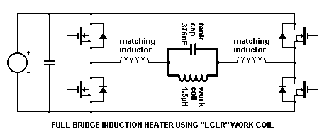
At still higher powers it is possible to use several seperate inverters effectively connected in parallel to meet the high load-current demands. However, the seperate inverters are not directly tied in parallel at the output terminals of their H-bridges. Each of the distributed inverters is connected to the remote work coil via its own pair of matching inductors which ensure that the total load is spread evenly among all of the inverters.
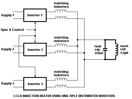
These matching inductors also provide a number of additional benefits when inverters are paralleled in this way. Firstly, the impedance BETWEEN any two inverter outputs is equal to twice the value of the matching inductance. This inductive impedance limits the "shoot between" current that flows between paralleled inverters if their switching instants are not perfectly synchronised. Secondly, this same inductive reactance between inverters limits the rate at which fault current rises if one of the inverters exhibits a device failure, potentially eliminating failure of further devices. Finally, since all distributed inverters are already connected via inductors, any additional inductance between the inverters merely adds to this impedance and only has the effect of slightly degrading current sharing. Therefore the distributed inverters for induction heating need not necessarily be located physically close to each other. If isolation transformers are included in the designs then they need not even run from the same supply!
Fault tolerance
The LCLR work coil arrangement is very well behaved under a variety of possible fault conditions.
- Open circuit work coil.
- Short circuit work coil, (or tank capacitor.)
- Shorted turn in work coil.
- Open circuit tank capacitor.
All of these failures result in an increase in the impedance being presented to the inverter and therefore a corresponding drop in the current drawn from the inverter. The author has personally used a screwdriver to short-circuit between turns of a work coil carrying several hundred amps. Despite sparks flying at the location of the applied short-circuit, the load on the inverter is reduced and the system survives this treatment with ease.
The worst thing that can happen is that the tank circuit becomes detuned such that its natural resonant frequency is just above the operating frequency of the inverter. Since the drive frequency is still close to resonance there is still significant current flow out of the inverter. But the power factor is reduced due to the detuning, and the inverter load-current begins to lead the voltage. This situation is undesirable because the load current seen by the inverter changes direction before the applied voltage changes. The outcome of this is that current is force-commutated between free-wheel diodes and the opposing MOSFET every time the MOSFET is turned on. This causes a forced reverse recovery of the free-wheel diodes whilst they are already carrying significant forward current. This results in a large current surge through both the diode and the opposing MOSFET that is turning on.
Whilst not a problem for special fast recovery rectifiers, this forced recovery can cause problems if the MOSFETs intrinsic body diodes are used to provide the free-wheel diode function. These large current spikes still represent a significant power loss and threat to reliability. However, it should be realised that proper control of the inverter operating frequency should ensure that it tracks the resonant frequency of the tank circuit. Therefore the leading power factor condition should ideally not arise, and should certainly not persist for any length of time. The resonant frequency should be tracked up to its limit, then the system shut-down if it has wandered outside of an acceptable frequency range.
Power control methods
It is often desirable to control the amount of power processed by an induction heater. This determines the rate at which heat energy is transferred to the workpiece. The power setting of this type of induction heater can be controlled in a number of different ways:
1. Varying the DC link voltage.
The power processed by the inverter can be decreased by reducing the supply voltage to the inverter. This can be done by running the inverter from a variable voltage DC supply such as a controlled rectifier using thyristors to vary the DC supply voltage derived from the mains supply. The impedance presented to the inverter is largely constant with varying power level, so the power throughput of the inverter is roughly proportional to the square of the supply voltage. Varying the DC link voltage allows full control of the power from 0% to 100%.
It should be noted however, that the exact power throughput in kilowatts depends not only on the DC supply voltage to the inverter, but also on the load impedence that the work coil presents to the inverter through the matching network. Therefore if precise power control is required the actual induction heating power must be measured, compared to the requested "power setting" from the operator and an error signal fed back to continually adjust the DC link voltage in a closed-loop fashion to minimise the error. This is necessary to maintain constant power because the resistance of the workpiece changes considerably as it heats up. (This argument for closed-loop power control also applies to all of the methods that follow below.)
2. Varying the duty ratio of the devices in the inverter.
The power processed by the inverter can be decreased by reducing the on-time of the switches in the inverter. Power is only sourced to the work coil in the time that the devices are switched on. The load current is then left to freewheel through the devices body diodes during the deadtime when both devices are turned off. Varying the duty ratio of the switches allows full control of the power from 0% to 100%. However, a significant drawback of this method is the commutation of heavy currents between active devices and their free-wheel diodes. Forced reverse recovery of the free-wheel diodes that can occur when the duty ratio is considerably reduced. For this reason duty ratio control is not usually used in high power induction heating inverters.
3. Varying the operating frequency of the inverter.
The power supplied by the inverter to the work coil can be reduced by detuning the inverter from the natural resonant frequency of the tank circuit incorporating the work coil. As the operating frequency of the inverter is moved away from the resonant frquency of the tank circuit, there is less resonant rise in the tank circuit, and the current in the work coil diminishes. Therefore less circulating current is induced into the workpiece and the heating effect is reduced.
In order to reduce the power throughput the inverter is normally detuned on the high side of the tank circuits natural resonant frequency. This causes the inductive reactance at the input of the matching circuit to become increasingly dominant as the frequency increases. Therefore the current drawn from the inverter by the matching network starts to lag in phase and diminish in amplitude. Both of these factors contribute to a reduction in the real power throughput. In addition to this the lagging power factor ensures that the devices in the inverter still turn on with zero voltage across them, and there are no free-wheel diode recovery problems. (This can be contrasted with the situation that would occur if the inverter were detuned on the low side of the work coil's resonant frequency. ZVS is lost, and the free-wheel diodes see forced reverse-recovery whilst carrying significant load current.)
This method of controlling power level by detuning is very simple since most induction heaters already have control over the operating frequency of the inverter in order to cater for different workpieces and work coils. The downside is that it only provides a limited range of control, as there is a limit to how fast power semiconductors can be made to switch. This is particularly true in high power applications where the devices may already be running close to maximum switching speeds. High power systems using this power control method require a detailed thermal analysis of the results of switching losses at different power levels to ensure device temperatures always stay within tolerable limits.
For more detailed information about power control by detuning see the new section below labelled "LCLR network frequency response."
4. Varying the value of the inductor in the matching network.
The power supplied by the inverter to the work coil can be varied by altering the value of the matching network components. The L-match network between the inverter and the tank circuit technically consists of an inductive and a capacitive part. But the capacitive part is in parallel with the work coil's own tank capacitor, and in practice these are usually one and the same part. Therefore the only part of the matching network that is available to adjust is the inductor.
The matching network is responsible for transforming the load impedance of the workcoil to a suitable load impedance to be driven by the inverter. Altering the inductance of the matching inductor adjusts the value to which the load impedance is translated. In general, decreasing the inductance of the matching inductor causes the work coil impedance to be transformed down to a lower impedance. This lower load impedance being presented to the inverter causes more power to be sourced from the inverter. Conversely, increasing the inductance of the matching inductor causes a higher load impedance to be presented to the inverter. This lighter load results in a lower power flow from the inverter to the work coil.
The degree of power control achieveable by altering the matching inductor is moderate. There is a also a shift in the resonant frequency of the overall system - This is the price to pay for combining the L-match capacitance and tank capacitance into one unit. The L-match network essentially borrows some of the capacitance from the tank capacitor to perform the matching operation, thus leaving the tank circuit to resonate at a higher frequency. For this reason the matching inductor is usually fixed or adjusted in coarse steps to suit the intended workpiece to be heated, rather than provide the user with a fully adjustable power setting.
5. Impedance matching transformer.
The power supplied by the inverter to the work coil can be varied in coarse steps by using a tapped RF power transformer to perform impedance conversion. Although most of the benefit of the LCLR arrangement is in the elimination of a bulky and expensive ferrite power transformer, it can cater for large changes in system parameters in a way that is not frequency dependent. The ferrite power transformer can also provide electrical isolation as well as performing impedance transformation duty to set the power throughput.
Additionally if the ferrite power transformer is placed between the inverter's output and the input to the L-match circuit its design constraints are relaxed in many ways. Firstly, locating the transformer in this position means that the impedances at both windings are relatively high. i.e. voltages are high and currents are comparitively small. It is easier to design a conventional ferrite power transformer for these conditions. The massive circulating current in the work coil is kept out of the ferrite transformer greatly reducing cooling problems. Secondly, although the transformer sees the square-wave output voltage from the inverter, it's windings carry currents that are sinusoidal. The lack of high frequency harmonics reduces heating in the transformer due to skin effect and proximity effect within the conductors.
Finally the transformer design should be optimised for minimum inter-winding capacitance and good insulation at the expense of increased leakage inductance. The reason for this is that any leakage inductance exhibited by a transformer located in this position merely adds to the matching inductance at the input to the L-match circuit. Therefore leakage inductance in the transformer is not as damaging to performance as inter-winding capacitance.
6. Phase-shift control of H-bridge.
When the work coil is driven by a voltage-fed full-bridge (H-bridge) inverter there is yet another method of achieving power control. If the switching instants of both bridge legs can be controlled independently then it opens up the possibility of controlling power throughput by adjusting the phase shift between the two bridge legs.
When both bridge legs switch exactly in phase, they both output the same voltage. This means there is no voltage across the
Hot
Relationship between induction frequency and quenching depth (hardening depth)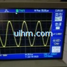
waveform of DSP induction heaters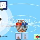
simulation of Faradays Law from University of Colorado Boulder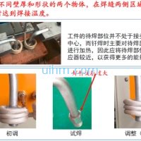
optimizing induction welding method for vehicle air conditioner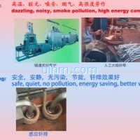
induction welding vehicle air conditioner vs common welding method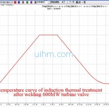
temperature curve of induction thermal treatment after welding 600MW turbine valve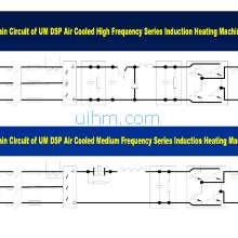
Main Circuit of UM DSP air cooled induction heaters
what is skin effect principle (magnetic force around induction coil)

